
 English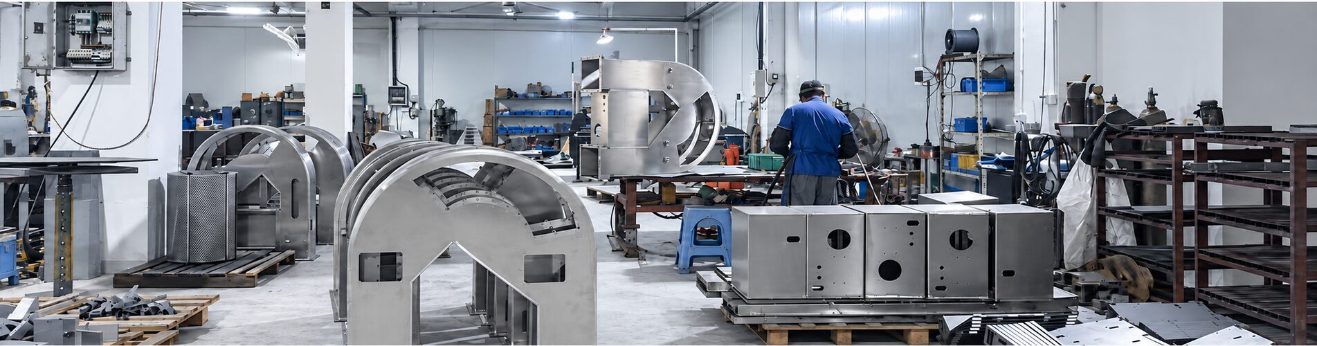

Two sheet metal parts with similar size and material can have very different manufacturing costs.
The difference is often in the drawing: tight tolerances, difficult bends, unnecessary welding, poor tool access or assembly details that add extra operations.
Most of these issues can be found before production starts.
At YT Manufacturing, we review drawings for enclosures, cabinets, machine frames, CNC machined parts and assembled products. Below are ten design issues we regularly check before quoting or prototyping a new project.
1. Using Tight Tolerances Everywhere
Not every dimension needs the same tolerance.
A mounting interface may need close control, while the overall size of a cover or non-critical panel may not.
When tight tolerances are applied everywhere, the manufacturer may need more time for machining, adjustment and inspection.
This becomes more noticeable on welded structures, where heat can affect flatness and alignment.
A practical drawing should make clear which dimensions really affect:
• Assembly
• Component fit
• Alignment
• Moving parts
• Sealing
• Machined interfaces
Use tighter tolerances where they matter and normal fabrication tolerances elsewhere.
2. Placing Holes Too Close to a Bend
Holes, slots and cutouts can deform when they are too close to a bend line.
Common problems include:
• Oval holes
• Stretched slots
• Distorted edges
• Poor screw alignment
• Position changes after bending
Sometimes the part can still be made, but it may require an extra operation after forming.
Leave enough clearance between bends and nearby features where the design allows it.
The required distance depends on material, thickness, bend radius, hole size and bend angle.
For parts with important mounting holes near bends, this should be checked before the sample is made.
3. Using an Impractical Bend Radius
A bend radius should match the material and sheet thickness.
A radius that is too small can increase the risk of cracking, surface damage or unstable forming, especially with thicker sheet or harder materials.
An unnecessarily large radius can create fit or appearance problems.
If the radius is not functionally critical, it is better to review it together with:
• Material grade
• Thickness
• Bend angle
• Part geometry
• Visible appearance
This gives more flexibility during forming without changing the function of the part.
4. Ignoring Bend and Tool Access
A shape may look simple in CAD but still be difficult to form on a press brake.
Deep flanges, closely spaced bends and enclosed shapes can interfere with the tooling or with previously formed sections.
Typical examples include:
• Narrow U-shaped channels
• Deep boxes
• Return flanges
• Multiple bends close together
• Bends that become blocked after earlier forming steps
The issue is often not one bend by itself, but whether the full bend sequence is practical.
A small change to flange length, bend order or part layout can sometimes avoid special tooling or extra welding.
5. Over-Specifying Welding and Weld Finishing
More welding does not always improve the product.
Long continuous welds can add heat, increase distortion and create more grinding work.
The same applies to weld appearance.
A visible corner may need to be smooth after finishing, while an internal structural weld may only need to meet the approved functional requirement.
On the drawing, it helps to distinguish between:
• Structural welds
• Visible cosmetic welds
• Hidden internal welds
This avoids unnecessary grinding and makes the expected finish easier to understand.
6. Using More Separate Parts Than Necessary
Every extra part adds another step.
It may need to be:
• Cut
• Handled
• Positioned
• Welded
• Fastened
• Inspected
In some designs, several small brackets or welded plates can be replaced by one formed sheet metal part.
Tabs, bends and formed features can sometimes reduce part count without changing the product function.
This does not mean every assembly should be redesigned into one piece. But when several simple parts only exist to create one basic shape, it is worth checking whether the structure can be simplified.
Fewer parts usually mean easier assembly and fewer opportunities for dimensional variation.
7. Forgetting Assembly and Maintenance Access
A fastener may fit in the CAD model but still be difficult to install.
The same problem can happen with welding or maintenance.
For example:
• A nut is too close to a wall for a tool to reach
• A mounting screw is blocked by another component
• A weld sits inside a narrow closed section
• A panel cannot be removed without taking apart half the product
These issues are common in:
• Electrical cabinets
• Self-service kiosks
• Machine enclosures
• Automation equipment
• Multi-part assemblies
When reviewing the design, check the actual assembly sequence.
Can the tool reach the fastener? Can the component be removed later? Will one installed part block another?
A small amount of extra access can save a lot of assembly time.
8. Leaving Surface Finish Until the End
Surface finishing should be considered before the metal design is finalized.
Powder coating, anodizing, galvanizing and other finishes can affect:
• Hole size
• Threads
• Tight-fitting features
• Electrical contact areas
• Masking
• Visible appearance
For example, coating buildup around a close-fitting feature may make assembly difficult.
Threads or contact surfaces may need to remain free from coating.
For visible stainless steel or aluminum parts, brushing direction and handling requirements may also matter before fabrication begins.
Where needed, show the following on the drawing:
• Finish type
• Color
• Visible surfaces
• Masking areas
• Areas to remain uncoated
• Brushing direction
9. Choosing Material Without Considering the Application
The same thickness does not mean the same performance.
Material choice should consider:
• Where the product will be used
• How it will be bent
• Whether it will be welded
• Whether corrosion resistance matters
• What finish is required
• Whether weight is important
If the grade has already been approved, specify it clearly on the drawing.
If the material is still open, describe the application and environment instead of writing only “steel” or “aluminum.”
That gives the manufacturer enough context to understand what the material needs to do.
10. Sending Inconsistent Drawing Revisions
A common problem is receiving a PDF, STEP file and BOM from different revisions.
One file may show the old hole pattern while another contains the latest version.
Before quotation or production, check that:
• The 2D drawing and 3D model match
• The BOM uses the same revision
• Material and finish information are current
• Previous versions are clearly replaced
For repeat production, any engineering change from the previous order should be marked clearly.
This avoids quoting or producing from an outdated file.
A Note on Large Welded Frames
Large welded structures need a different approach from small sheet metal parts.
Welding can affect flatness and alignment, while some mounting surfaces or hole patterns may need machining after fabrication.
If a frame includes critical interfaces, mark them clearly on the drawing.
Typical examples include:
• Mounting surfaces
• Datum points
• Critical hole patterns
• Machined interfaces
This allows welding and post-weld machining to be planned as one manufacturing sequence.
For a large equipment frame, controlling a few important mounting surfaces is usually more practical than applying machining-level tolerances to the entire welded structure.
When Is a DFM Review Useful?
A simple laser-cut plate may not need much discussion.
DFM becomes more useful when a project includes:
• Several bends
• Welded structures
• Tight assembly interfaces
• Machined surfaces
• Multiple assembled parts
• Visible finished surfaces
• New prototype designs
The review may lead to something as small as moving a hole, changing a flange, opening an assembly gap or adjusting a non-critical tolerance.
These changes are much easier to make before the first sample is produced.
A Practical Sheet Metal Drawing Checklist
Before sending a drawing for quotation or production, check:
• Are the critical tolerances clearly marked?
• Are holes far enough from bends?
• Is the bend radius suitable for the material and thickness?
• Can the bends actually be made with available tool access?
• Are weld requirements clearly defined?
• Are cosmetic weld requirements limited to visible areas?
• Can tools reach the required fasteners and joints?
• Has surface finishing been considered?
• Is the material grade clearly specified?
• Do the 2D drawing, 3D model and BOM match?
You do not need to solve every manufacturing question before contacting a supplier.
But a clear drawing makes it much easier to identify which details need discussion before the first prototype.
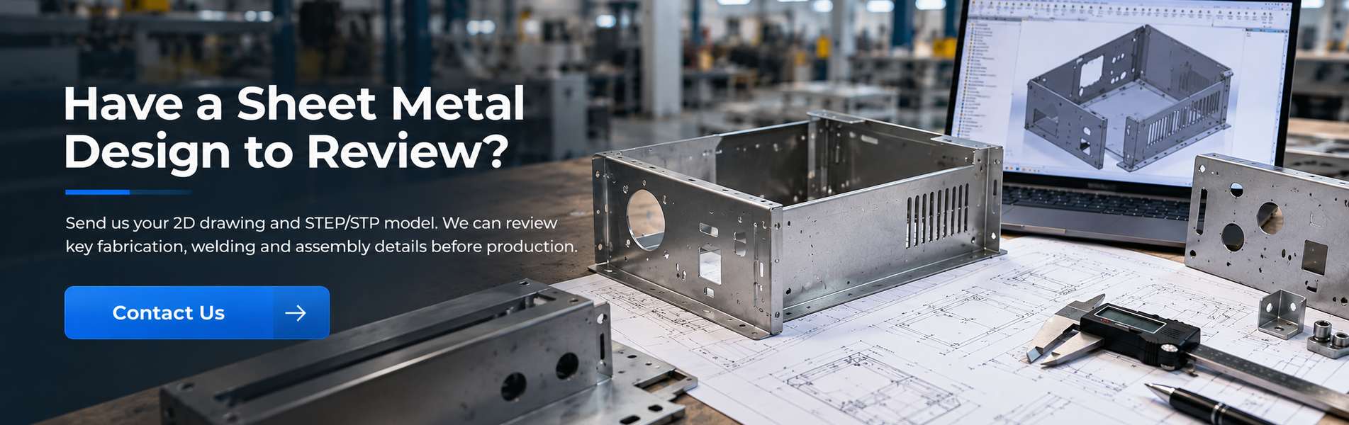
Have a Sheet Metal Design to Review?
Send your 2D drawing and STEP/STP model together with the material, quantity, finish and application requirements.
YT Manufacturing can review manufacturability for sheet metal fabrication, bending, welding, CNC machining, finishing and assembly according to the project scope.